Task C - Operation of Systems - Sub-Section 4:: Powerplant and Propeller
Lesson Overview
- Objective
-
To discuss the powerplant and propeller system with the student so they better understand standard operations.
- Reference
-
-
(PHAK) FAA-H-8083_25B
-
(AFH) FAA-H-8083-3B
-
PA-28-151 POH
-
- Elements
-
-
Trim System
-
Types of Trim
-
Trim for the PA-28-151
-
How to Trim
-
Why You Trim
-
- Equipment
-
-
Whiteboard
-
Engine Operator’s Manual
-
Pilots Handbook of Aeronautical Knowledge
-
- Schedule
-
-
Discuss objectives
-
Review material
-
Development
-
Conclusion
-
- Instructor Actions
-
-
Discuss Objectives
-
Present Material
-
Ask and Answer Questions
-
- Student Actions
-
-
Participate in discussion
-
Take notes
-
Ask and Respond to Questions
-
- Completion Standards
-
The students will understand basic power plant operations from intake to power output students will also be able to understand the constant speed propeller and governor functionality.
Instructor Notes
- Attention
-
Engines do more than just eat cash.
- What
-
What an Engine, Powerplant and Propellor are.
- Why
-
In order for (our) plane to fly, it needs an engine that produces excess thrust to create enough lift.
Lesson Details
Introduction
The engine is controlled by a throttle knob, as well as a mixture control knob. These are mounted on the panel between the two pilot’s seating positions.
The Piper Warrior weighing in at 2325 pounds max gross weight would be pretty hard to taxi without the assistance of the Lycoming O-360’s. The O-360-E3D’s equipped with a 74`" propeller would be a recipe for success.
Using the acronym LHAND we can quickly determine simple specifications of the power plant.
-
Lycoming
-
Horizontally opposed
-
Air-cooled
-
Normally aspirated
-
Direct drive
In order for the engine to produce the power needed to turn the propeller, a few important steps must take place.
Engine Process
There are four steps in the engine process in order to produce power.
The first step involves the piston in the cylinder to transition downward thus pulling in the air and fuel mixture through the intake manifold from the carburetor. This step is called the first or intake stroke of the four-step engine process. Once the fuel and air mixture has entered the cylinder, the piston begins to move upward and compress the mixture. The process is known as the second or compression stroke and makes for an easy ignition of the mixture. As the piston reaches the top of the cylinder, the spark from the spark plug ignites the mixture in a process called third, combustion, or power stroke. This combustion forces the piston back down and in turn, rotates the crankshaft for the distribution of mechanical energy. The last step in the four-step process is the exhaust stroke. As the piston returns to the top forcing the burnt mixture out, the four-step process is ready to start again.
Airflow for air cooling and carburetor intake
During the intake process, air is funneled precisely through the engine compartment or cowl with the use of shrouds. The carburetor, mentioned in the fuel system is located on the rear, lower side of the engine.
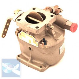
The funneled air is ingested through the carburetor after providing cooling to the engine in turn can help prevent carburetor ice from forming. The air intake has an air filter and bracket system to help remove particles before entering the carburetor. Once the air has reached the carburetor, the engine intake process begins. The use of carburetor heat is also an alternate source of air should the filter become clogged in flight.
The Propeller system
The Warrior is equipped with a Sensenich two-bladed, fixed pitch, metal propeller. Propeller diameter is 74 inches. Maximum RPM (red line) is 2700 RPM.
Conclusion
Its obvious of how important engines are for a safe journey in the skies. Knowing about how engines work help us better understand how to get maximum life out of them, and troubleshoot in case something goes wrong while we’re in the air.
ACS Requirements
To determine that the applicant exhibits instructional knowledge of the elements of principles of flight by describing:
-
Primary and secondary flight controls
-
Trim
-
Powerplant and propeller
-
Landing gear
-
Fuel, oil, and hydraulic
-
Electrical
-
Avionics including autopilot
-
Pitot static, vacuum/pressure and associated instruments
-
Environmental